Frame and tray
Parts 1-7 bolt together as the sealed chassis: skid plate, battery tray, side rails, front/rear crossmembers, and electronics deck.
 K2Aley GAR-BOT Connection Illustration
Full parts breakdown and connection map
This page combines the printed frame parts, claw parts, electronics, motors, LEDs, servo boards, touchscreen, remote transmitter, and sealed wiring routes into one numbered assembly illustration.
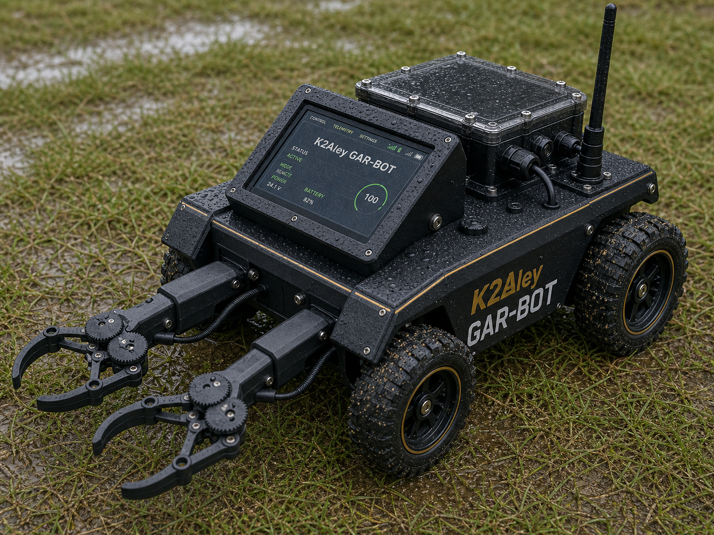
Full illustration
The numbers match the printed-parts table. Lettered hardware groups show the electronics and purchased parts. Colored lanes show what connects mechanically, electrically, and by USB/data.
The map uses numbered callouts to keep the illustration readable. Match each number to the printed-parts inventory below for the exact STL file, dimensions, and connection point.
Connection order
The order below keeps the heavy parts low, the serviceable electronics accessible, and the claw/lighting harnesses away from moving joints.
Parts 1-7 bolt together as the sealed chassis: skid plate, battery tray, side rails, front/rear crossmembers, and electronics deck.
Parts 13-14 protect the IBT-2 boards and motor corners. Four direct-drive motors fasten at the rail/crossmember corners.
Parts 8-12 install on the electronics deck. The RP5, relay HAT, buck converters, fuse bus, and LoRa USB bridge stay inside the sealed bay.
Parts 15-25 build the shoulder bridge, round shoulder mounts, left/right claw bases, wrists, palms, fingers, link bars, and gear covers.
Parts 27-31 mount the 7 inch USB touchscreen above the electronics bay with left/right uprights, top bar, bezel, and rain hood.
Nine RGB LED star modules mount under the chassis. Side servos sit in parts 26 and tilt the light rails from spare claw-board channels.
RP5 USB goes to left claw board, right claw board, 7 inch touchscreen, and LoRa bridge or powered hub. Pi Wi-Fi remains available for setup/API.
Parts 36-38 house the Raspberry Pi Zero 2 W, Pico Voice, and remote LoRa bulkhead. No Pro Mini and no nRF24L01+ are used.
Real component photos
These photos are the real part references already saved in the GAR-BOT project.
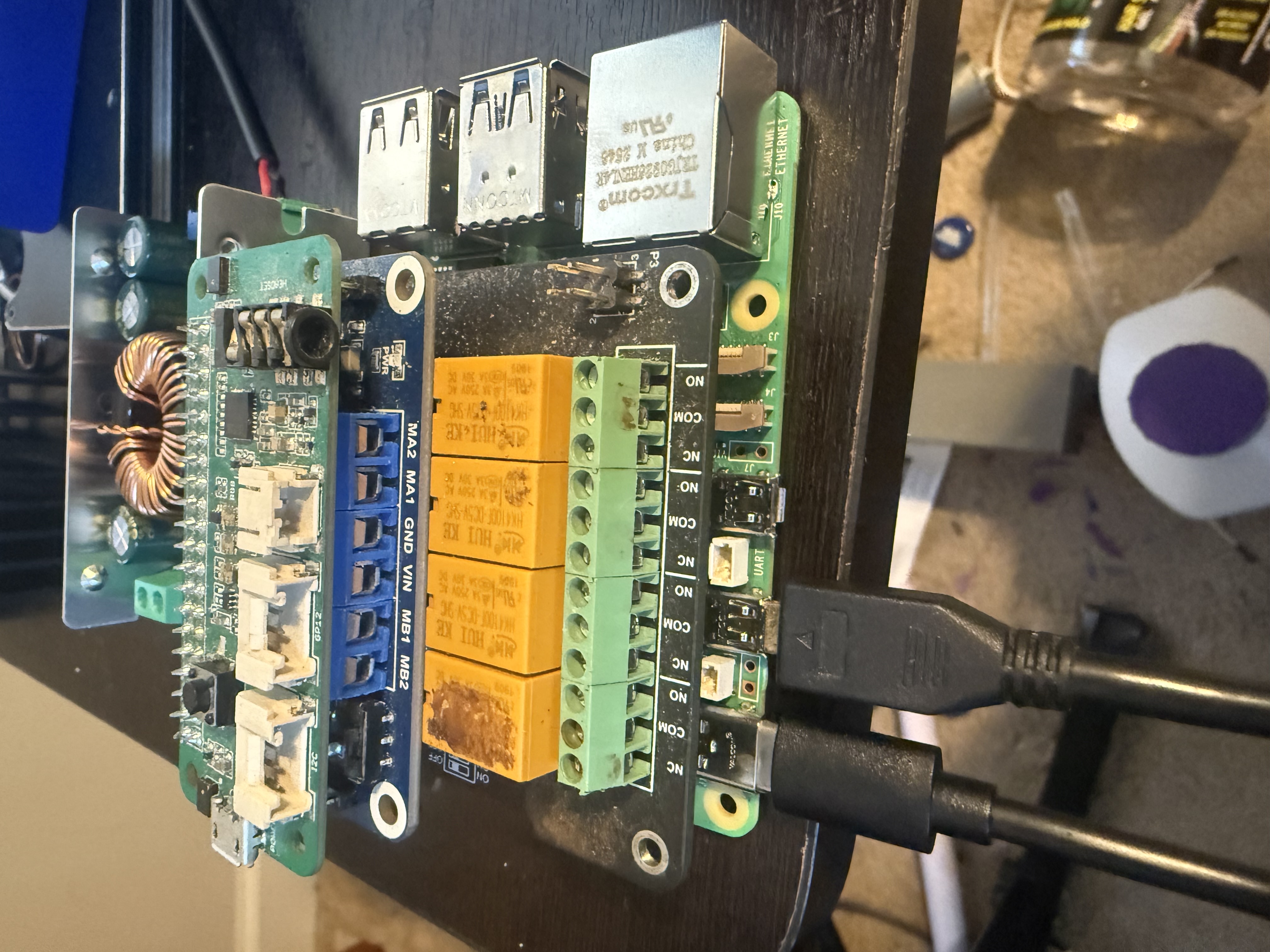
Bolts inside electronics bay 8 and receives 5.1V buck power.
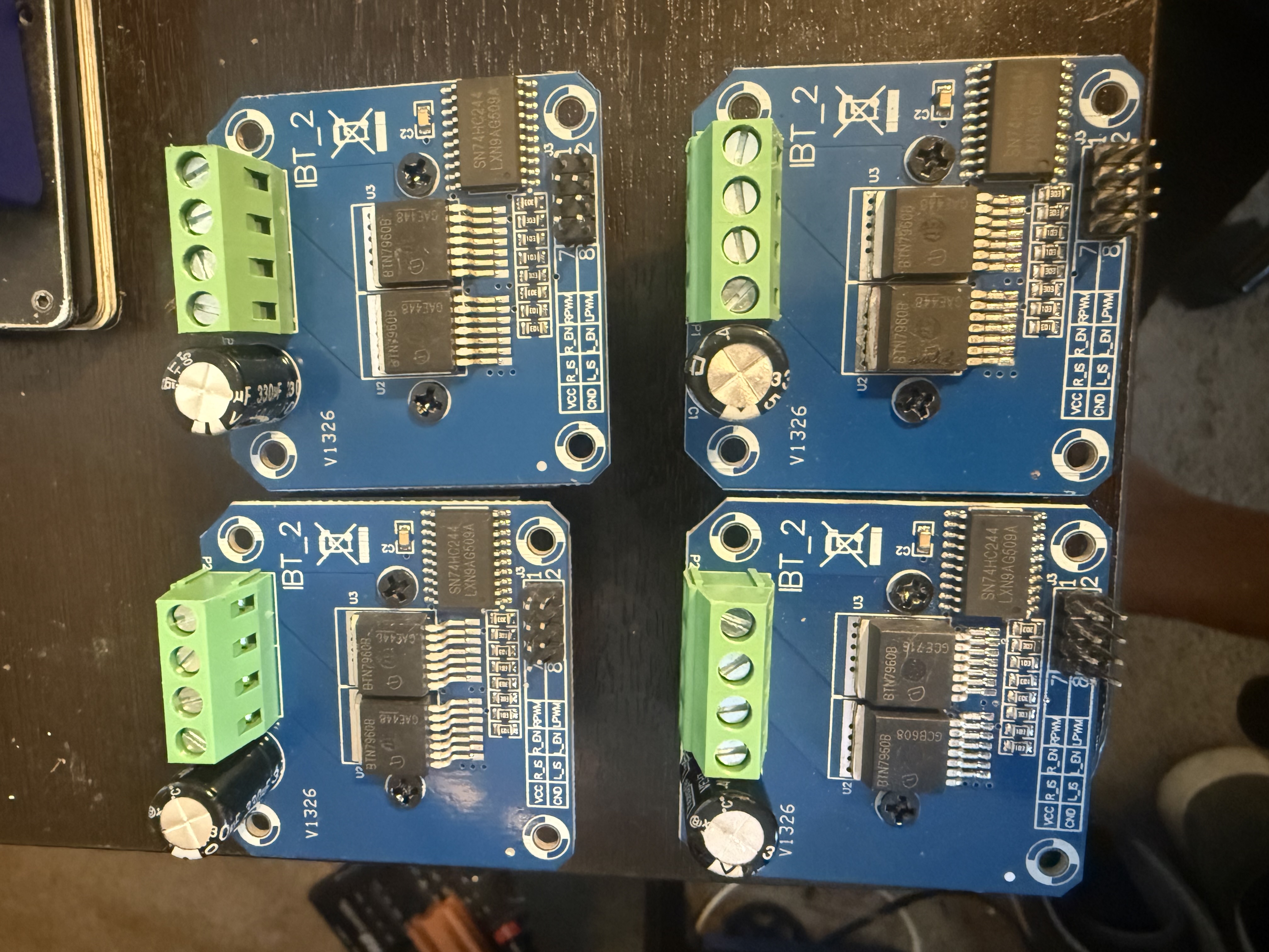
Four covered drivers connect RP5 GPIO to the four 24V motors.
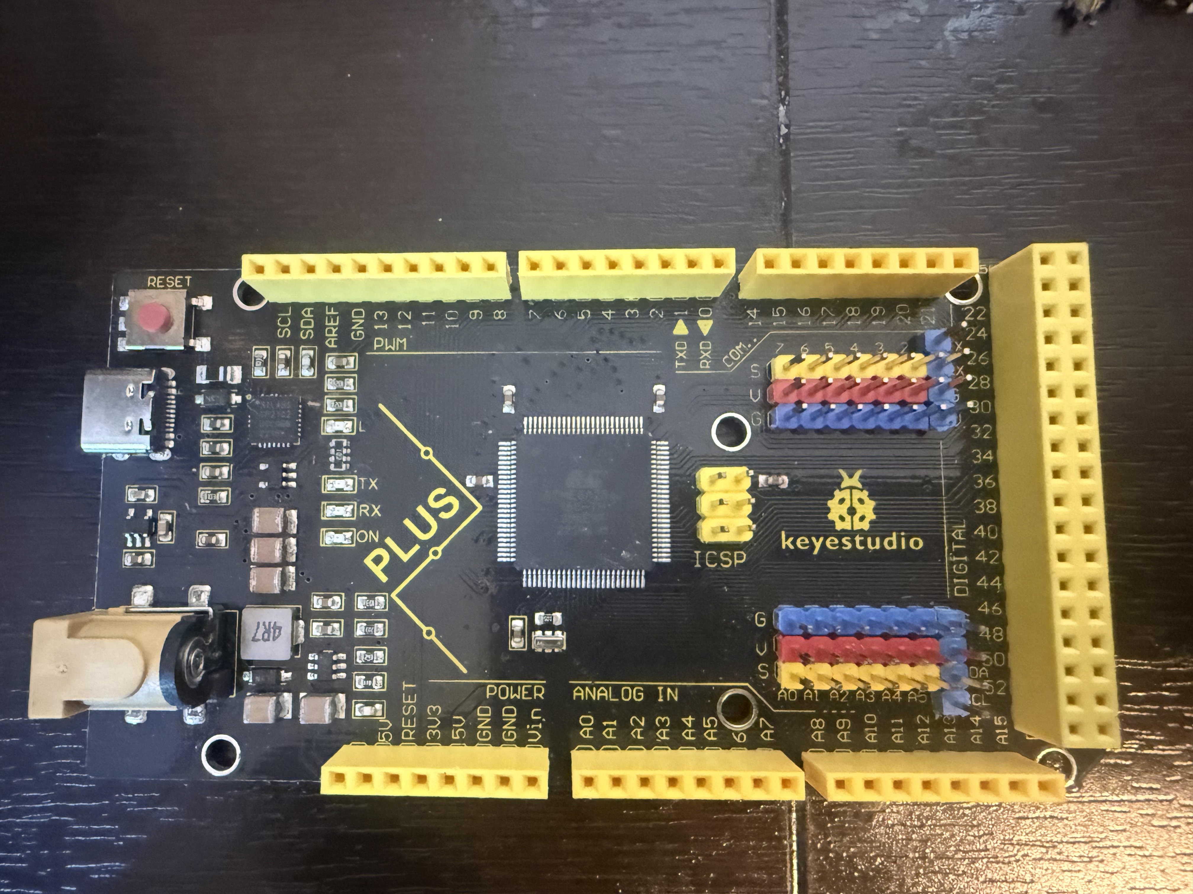
Left and right USB servo boards drive the claws and side light servos.
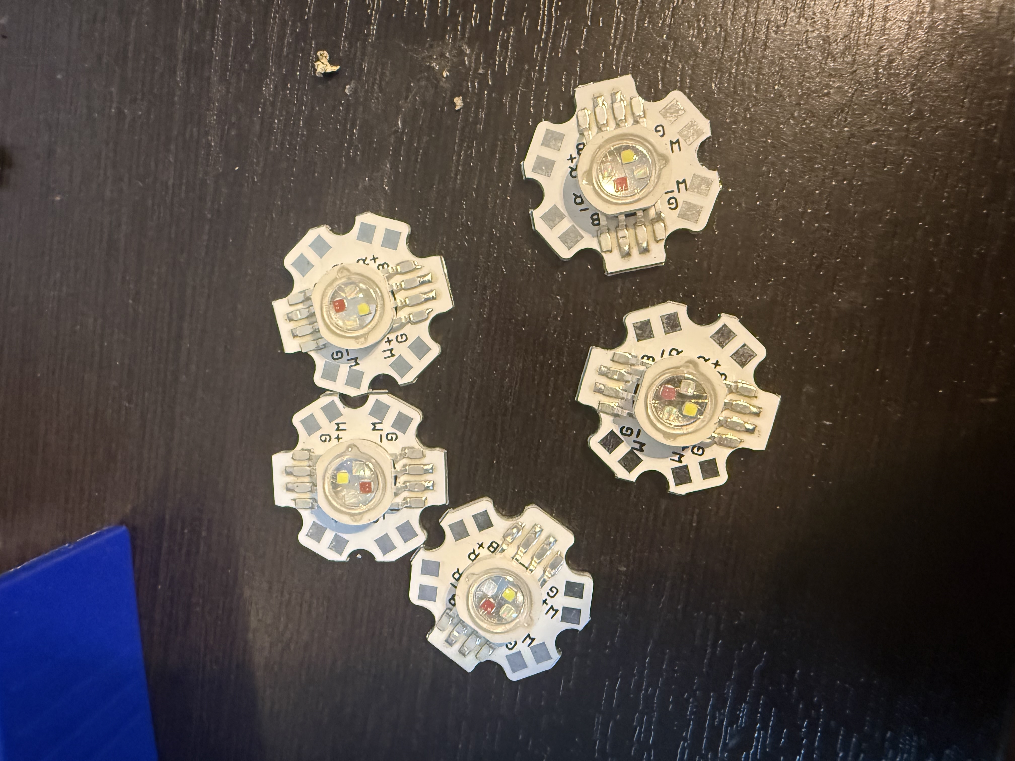
Sealed underbody ground-effect modules in three banks.
Complete printed-parts inventory
Part dimensions are from the recreated detailed STL manifest. All listed STL files passed the current mesh integrity audit.
| No. | STL file | Connects to | Dimensions | Route / purpose |
|---|---|---|---|---|
| 1 | frame_bottom_skid_plate.stl | 2, 3, 4, 5, 6 | 280.00 x 170.00 x 18.00 mm | Mechanical base. Bottom shield and main chassis datum. |
| 2 | frame_center_battery_tray.stl | 1, 7, H8 | 230.00 x 128.00 x 20.00 mm | Holds the 24V battery pack low in the chassis. |
| 3 | frame_left_side_rail.stl | 1, 5, 6, 14 | 320.00 x 32.00 x 24.00 mm | Left side frame rail and left motor/shield mounting edge. |
| 4 | frame_right_side_rail.stl | 1, 5, 6, 14 | 320.00 x 32.00 x 24.00 mm | Right side frame rail and right motor/shield mounting edge. |
| 5 | frame_front_crossmember.stl | 1, 3, 4, 15 | 260.00 x 38.00 x 34.00 mm | Front shoulder and motor corner structure. |
| 6 | frame_rear_crossmember.stl | 1, 3, 4 | 260.00 x 38.00 x 39.00 mm | Rear motor corner structure and rear body tie. |
| 7 | frame_electronics_deck_plate.stl | 2, 8, 12, H1 | 236.00 x 166.00 x 8.00 mm | Deck plate for electronics bay, RP5 stack, bucks, and fuse bus. |
| 8 | electronics_bay.stl | 7, 9, 10, 33 | 230.00 x 160.00 x 61.00 mm | Sealed electronics tub with internal standoffs for RP5, buck converter, Pico Voice I2C board, and LoRa bridge wiring. |
| 9 | gasketed_lid.stl | 8, 33, 35 | 230.00 x 160.00 x 7.00 mm | Service lid. Add gasket before splash testing. |
| 10 | cable_gland_panel.stl | 8, 11, 32 | 130.00 x 52.00 x 10.20 mm | Panel for cable exits, gland nuts, and sealed harness routing. |
| 11 | drip_loop_cable_clip.stl | 10, 24, 25, H12 | 28.00 x 12.00 x 10.00 mm | Clips harness loops below gland height so water drips away. |
| 12 | buck_converter_cover.stl | 7, H6, H7 | 78.00 x 50.00 x 29.60 mm | Covers 5.1V RP5 buck and 6V servo/lighting buck area. |
| 13 | ibt2_driver_cover.stl | 7, H3 | 62.00 x 55.00 x 25.60 mm | Covers each IBT-2 driver board. Use four driver positions. |
| 14 | motor_splash_shield.stl | 3, 4, 5, 6, H4 | 120.00 x 78.00 x 30.20 mm | Protects motor corners from splash and wiring snag points. |
| 15 | frame_claw_bridge.stl | 5, 16, 17, 18 | 245.00 x 120.00 x 33.60 mm | Top shoulder bridge carrying both claws above the front shoulders. |
| 16 | round_shoulder_mount.stl | 15, 17, 18 | 86.00 x 86.00 x 18.00 mm | Round pivot plate under each top-shoulder claw base. |
| 17 | left_claw_base_mount.stl | 15, 16, 19, 24 | 96.00 x 72.00 x 26.40 mm | Left top-shoulder claw saddle with heat-set insert pockets and cable exit. |
| 18 | right_claw_base_mount.stl | 15, 16, 19, 24 | 96.00 x 72.00 x 26.40 mm | Right top-shoulder claw saddle with mirrored cable exit. |
| 19 | wrist_servo_cradle.stl | 17, 18, 20, H14 | 64.00 x 38.00 x 26.20 mm | Holds the claw wrist servo at each shoulder. |
| 20 | claw_palm.stl | 19, 21, 22, 23 | 62.00 x 34.00 x 13.80 mm | Main palm block for each gripper. |
| 21 | claw_gripper_finger.stl | 20, 22 | 92.00 x 10.00 x 17.80 mm | Curved gripper fingers. Print mirrored sets as needed. |
| 22 | claw_link_bar.stl | 20, 21, 23 | 74.00 x 9.00 x 6.40 mm | Parallel link bars that synchronize the claw fingers. |
| 23 | claw_gear_guard.stl | 20, 21, H14 | 58.80 x 58.80 x 8.60 mm | Guards exposed claw gear/pivot area. |
| 24 | claw_controller_cover.stl | 17, 18, H5 | 88.00 x 55.00 x 21.80 mm | Covers the left/right claw USB servo boards. |
| 25 | forearm_wire_cover.stl | 17, 18, 19, 24 | 130.00 x 24.00 x 18.00 mm | Covers claw forearm wiring from base to wrist. |
| 26 | sealed_servo_pocket.stl | 3, 4, H13, H12 | 48.00 x 42.00 x 31.80 mm | Side-mounted servo pocket for up/down ground-effect light movement. |
| 27 | touchscreen_bezel.stl | 29, 30, H11 | 205.00 x 135.00 x 6.80 mm | Front trim for the 7 inch USB touchscreen. |
| 28 | touchscreen_rain_hood.stl | 27, 31 | 223.00 x 98.00 x 16.60 mm | Rain hood above the touchscreen bezel. |
| 29 | frame_touchscreen_upright_left.stl | 7, 27, 31 | 58.00 x 24.00 x 145.00 mm | Left touchscreen upright. |
| 30 | frame_touchscreen_upright_right.stl | 7, 27, 31 | 58.00 x 24.00 x 145.00 mm | Right touchscreen upright. |
| 31 | frame_touchscreen_top_bar.stl | 28, 29, 30 | 225.00 x 28.00 x 17.80 mm | Top crossbar tying the touchscreen uprights together. |
| 32 | lora_antenna_bulkhead_guard.stl | 8, 10, H10 | 42.00 x 42.00 x 14.80 mm | Guard around robot-side LoRa antenna or cable bulkhead. |
| 33 | k2aley_lid_badge.stl | 9 | 150.00 x 48.00 x 5.80 mm | Top lid branding badge. |
| 34 | k2aley_side_badge.stl | 3, 4, 8 | 185.00 x 40.00 x 5.80 mm | Side branding badge. |
| 35 | water_warning_badge.stl | 9, 8 | 180.00 x 62.00 x 5.80 mm | Wet-use warning badge: electronics must stay covered. |
| 36 | remote_zero2w_pico_voice_case_front.stl | 37, 38, H2 | 190.00 x 128.00 x 37.00 mm | RC-style transmitter front shell for joysticks, pots, switches, buttons, RP Zero 2 W, Pico Voice, and LoRa. |
| 37 | remote_zero2w_pico_voice_case_back.stl | 36, 38, H2 | 190.00 x 128.00 x 28.00 mm | RC-style transmitter back tray with 2x18650 holder space and PCB/control supports. |
| 38 | remote_lora_antenna_bulkhead.stl | 36, 37, H10 | 42.00 x 42.00 x 14.80 mm | Remote-side LoRa antenna or cable bulkhead guard. |
| 39 | one_piece_body_cover.stl | 7, 8, 15, 27, 28 | 340.00 x 200.00 x 52.00 mm | One-piece upper cover around the chassis deck, electronics area, touchscreen window, and shoulder-claw reliefs. |
| 40 | one_piece_bottom_skid_plate.stl | 1, 3, 4, 5, 6 | 360.00 x 220.00 x 24.40 mm | Mechanical base. Large underbody skid with wheel reliefs, drain slots, side runners, center keel, and heat-insert pockets. |
| 41 | telescopic_claw_outer_sleeve.stl | 17, 18, 42, 43 | 118.00 x 46.00 x 27.00 mm | Outer sliding claw sleeve mounted ahead of each shoulder claw base. |
| 42 | telescopic_claw_inner_slider.stl | 20, 21, 41, 43 | 140.00 x 28.00 x 19.00 mm | Sliding front reach member for the telescopic claw assembly. |
| 43 | telescopic_claw_lock_collar.stl | 41, 42 | 34.00 x 56.00 x 30.80 mm | Collar that clamps and indexes the telescopic slider. |