1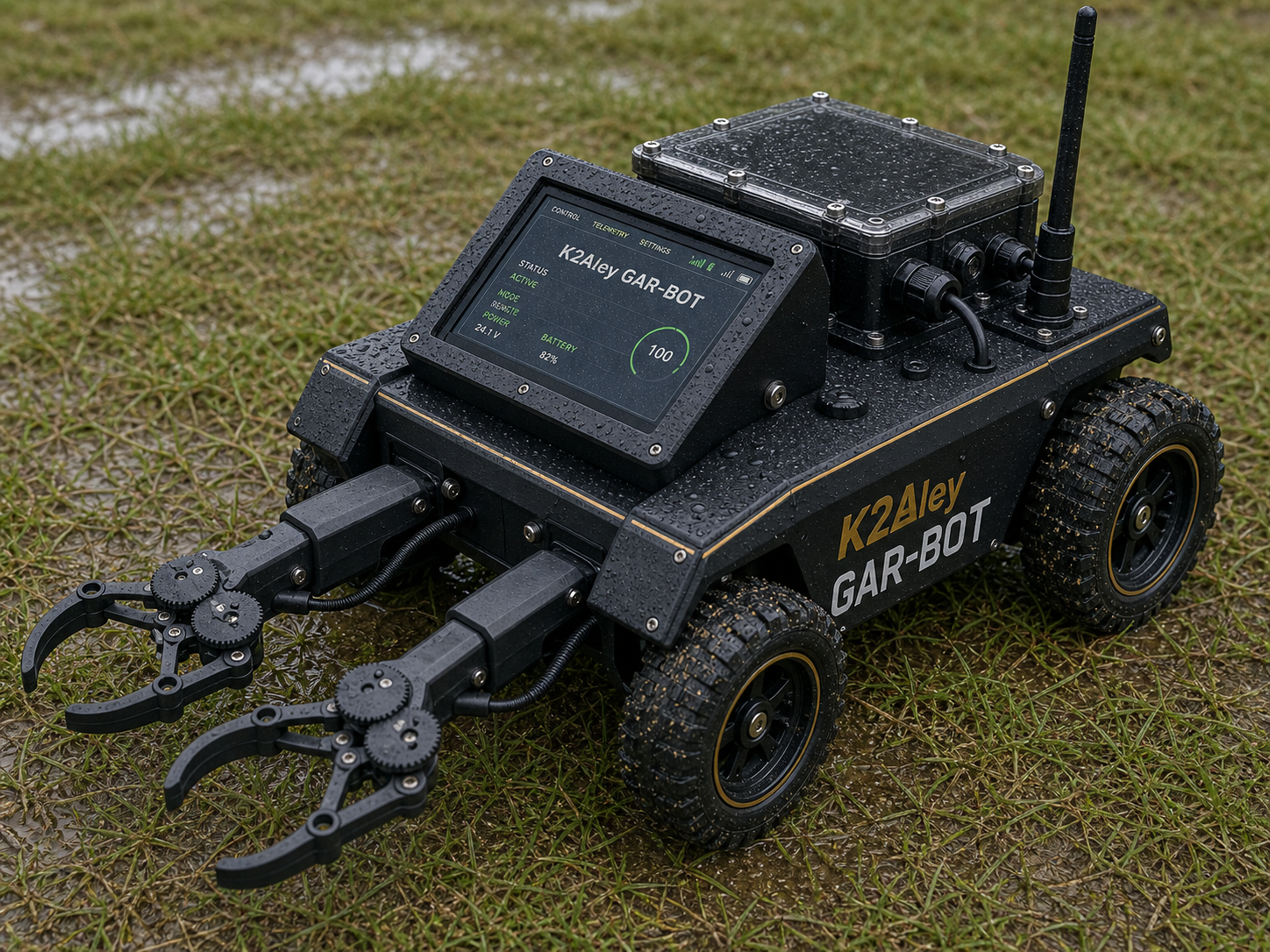
Build the frame rectangle
Side rails run front-to-back. Crossmembers square the ends. Skid plate, tray, and deck stack through the heat-set insert holes.
89101112131415
Numbered real-photo breakdown
This page combines the real hardware photos already in the GAR-BOT package with numbered rendered pictures from the actual exported STL files. The photo cards show physical components; the render cards are generated from the final printable part files.
How the parts fit together
The center picture shows where each numbered group lands on GAR-BOT. The stage cards show the build order and the exact part numbers used in that area.
Side rails run front-to-back. Crossmembers square the ends. Skid plate, tray, and deck stack through the heat-set insert holes.
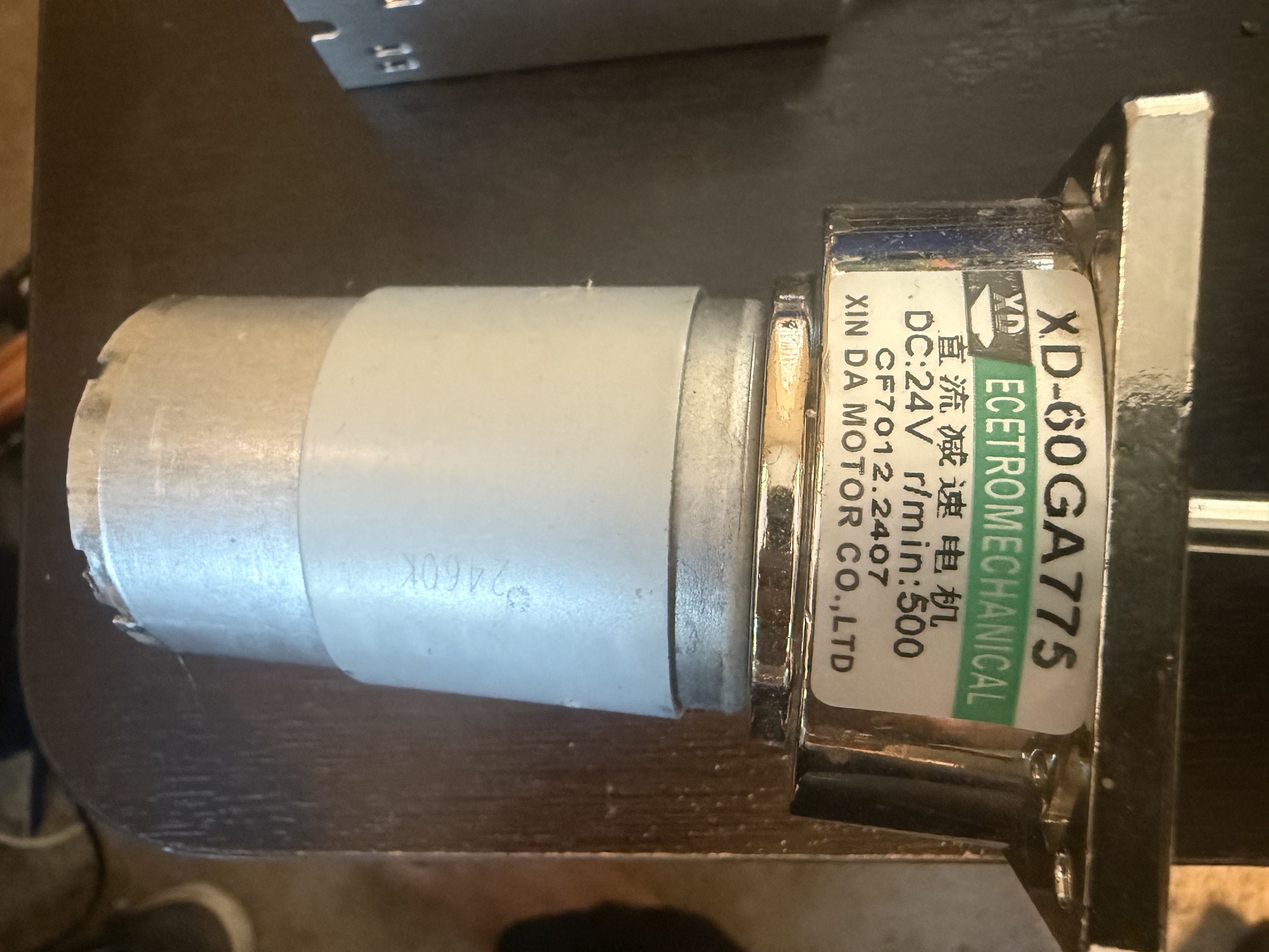
Each 24V motor mounts at a wheel corner and direct-drives its own wheel. Driver boards stay protected, with covers over power electronics, splash shields at the motor area, and drip-loop cable clips at the exits.
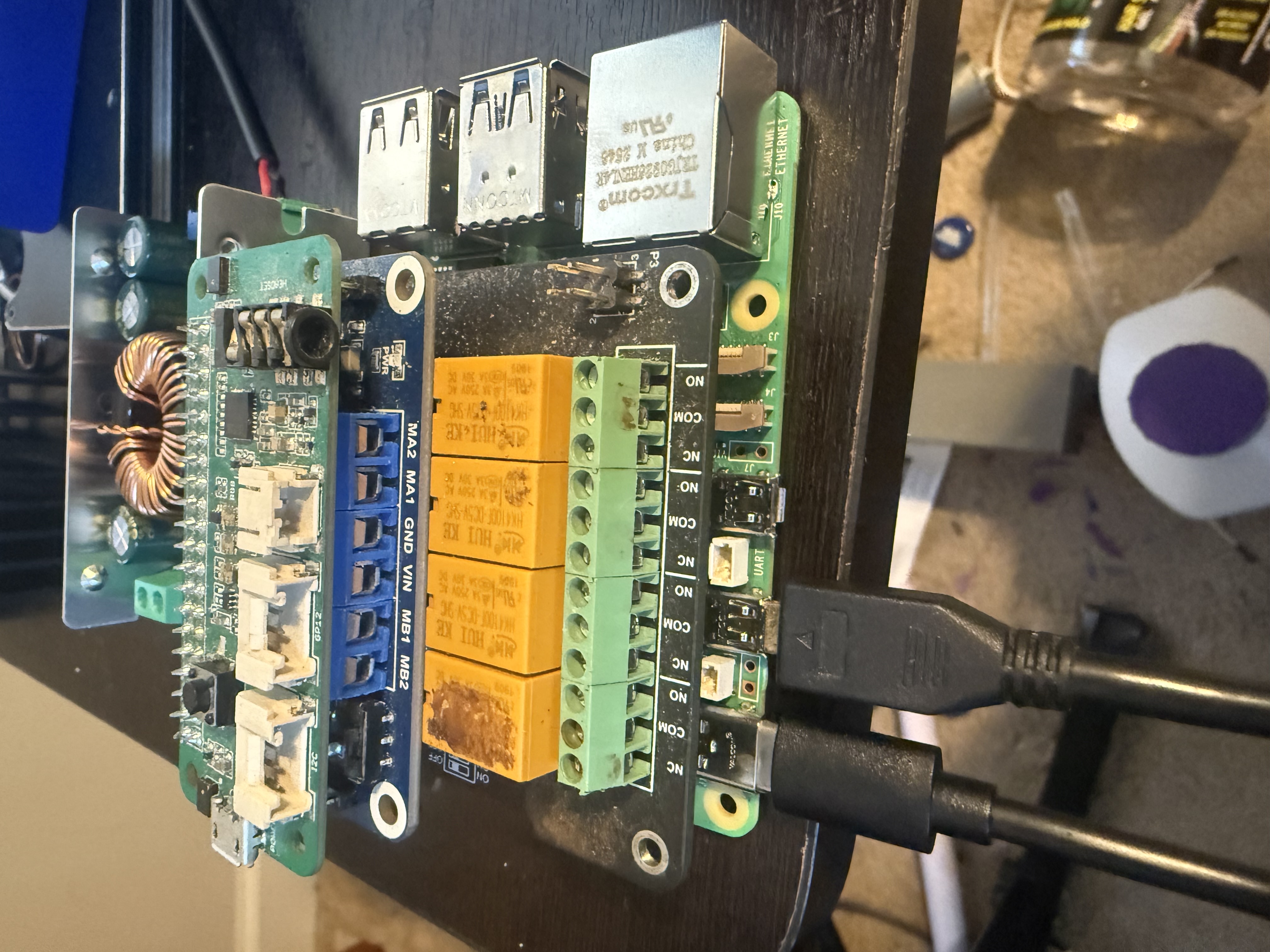
The RP5, buck converter, and Pico Voice I2C board sit on the bay's internal standoffs. The gasketed lid closes the top, and the gland panel keeps wire exits protected.
The uprights bolt to the deck, the top bar ties them together, and the bezel/rain hood protect the 7 inch USB touchscreen.
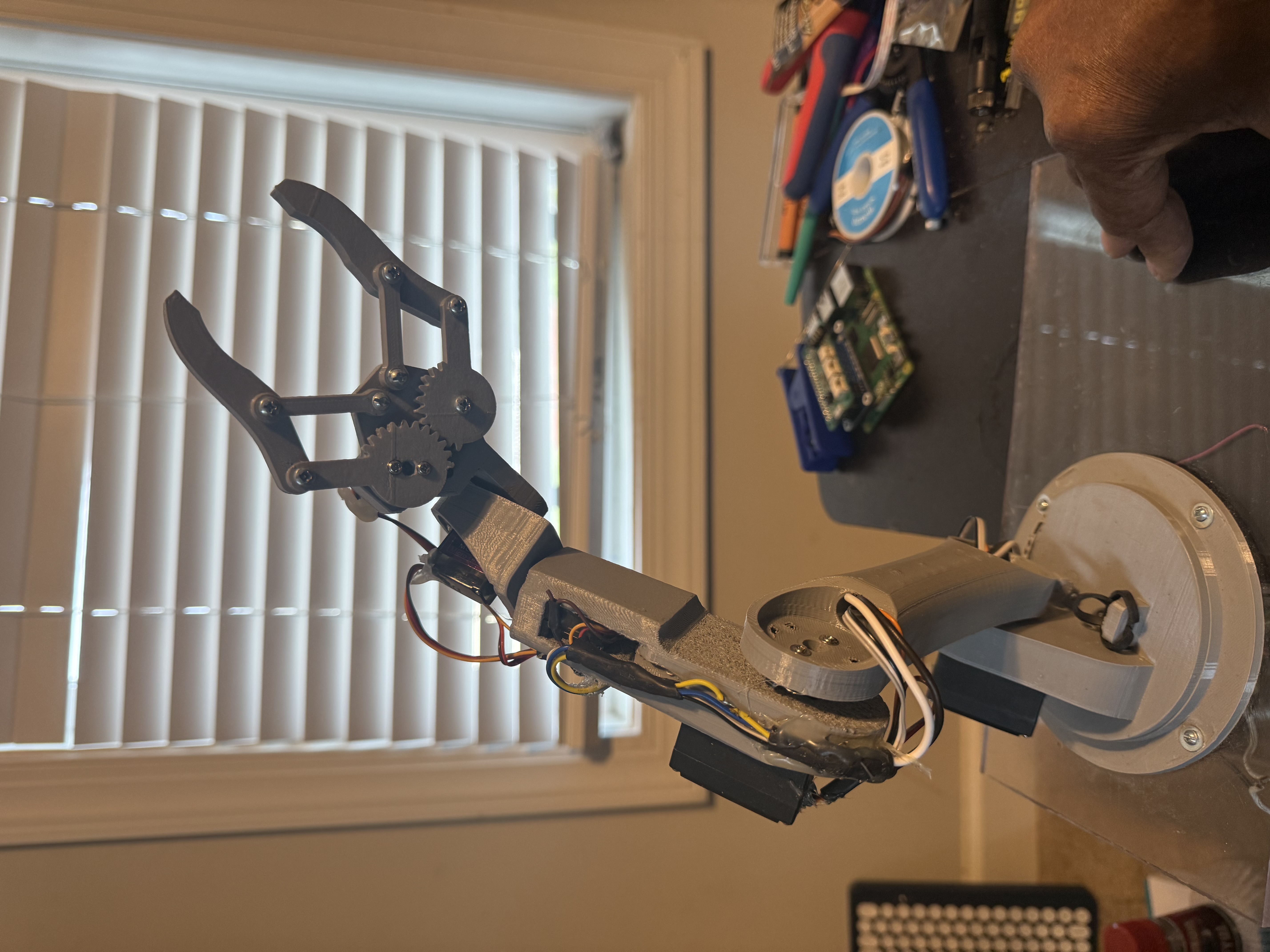
Left and right base mounts bolt down onto the top shoulder pads of the bridge. Shoulder pivots, servo pockets, palms, fingers, link bars, gear guards, and wire covers complete each claw.
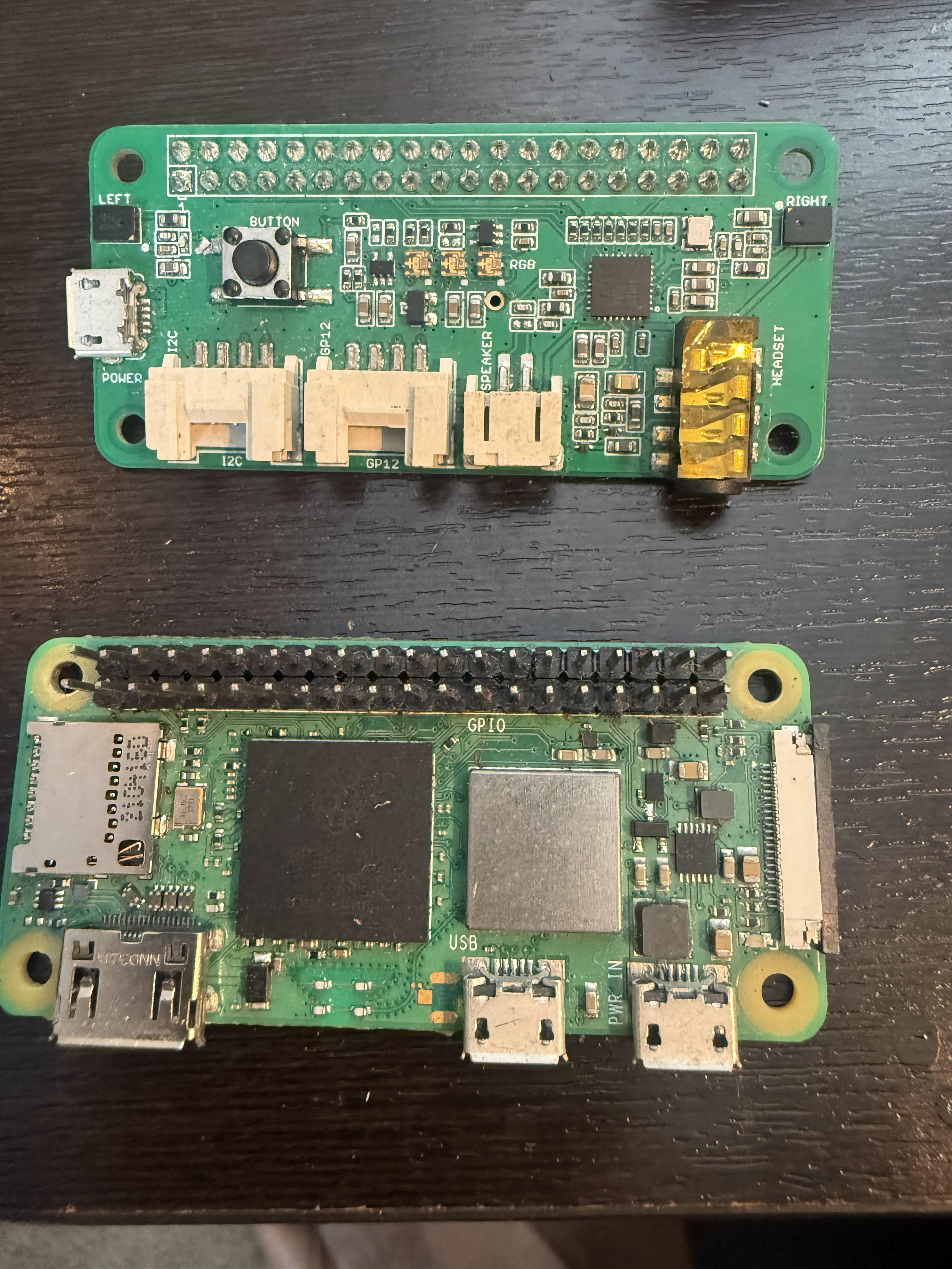
The RP Zero 2 W and Pico Voice boards fit into the remote case. The LoRa antenna bulkhead mounts through the case wall.
K2Aley and GAR-BOT badges mount on the lid and sides. The water warning badge marks the no-exposed-electronics rule.
Physical component photos
These are the actual photos from the project folders and OneDrive references.
Actual STL renders
The browser renders each image from the copied STL file, then stamps the part number, label, dimensions, and PASS status on the card.