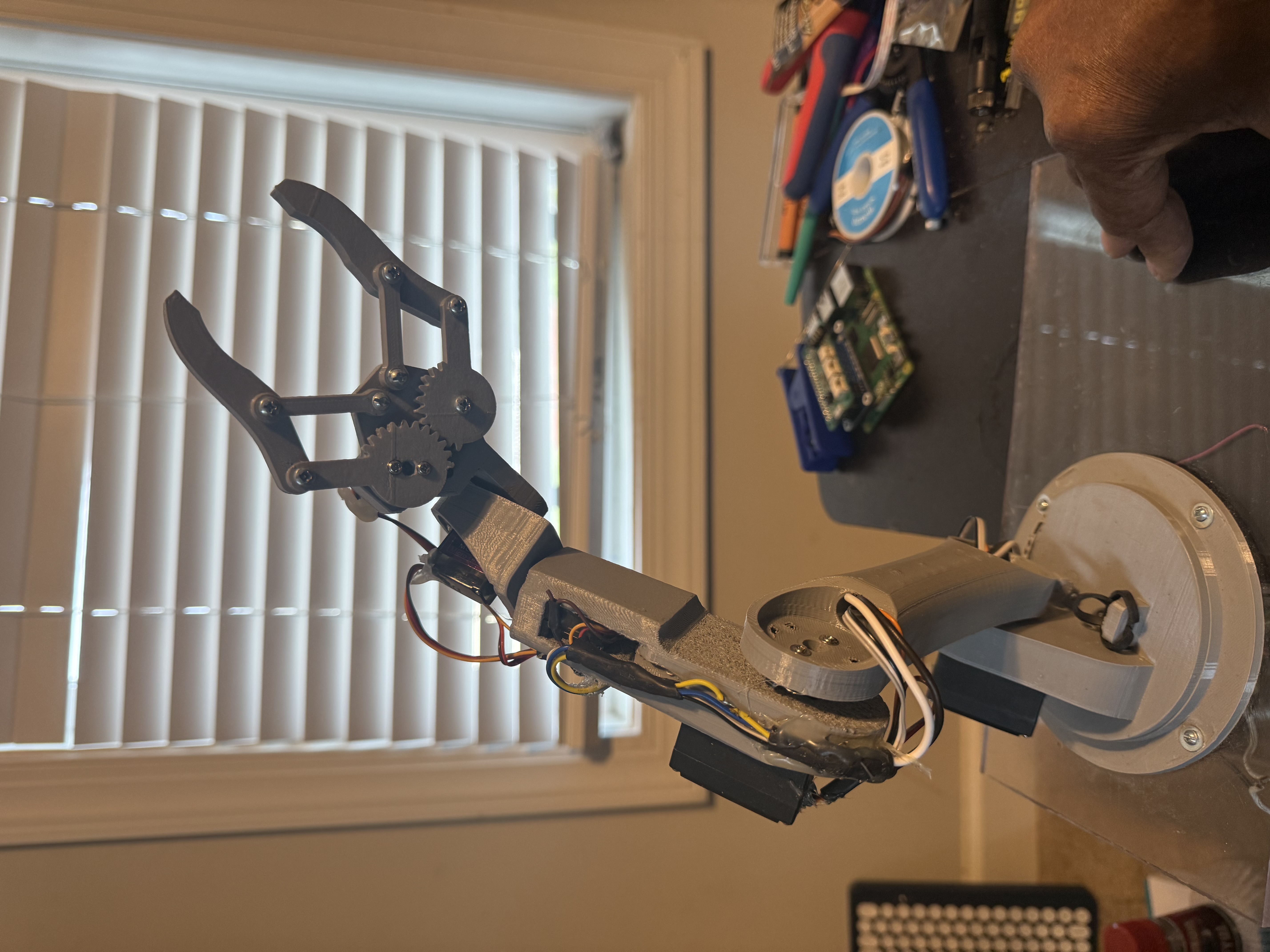
1. Two claw assembly
Reference for the two top-mounted claw shapes and pivots.
Build, wire, test, operate, and upgrade the K2Aley GAR-BOT two-claw dry-use rover prototype.
This manual uses the same part numbers from the numbered photo breakdown. Follow the build stages in order: frame, drive, protective electronics bay, touchscreen, claws, ground-effect lighting, remote, branding, wiring, sealing upgrade checks, and operation.
Open the complete GAR-BOT BOM for hardware, electronics, printed parts, and sealing upgrade materials.
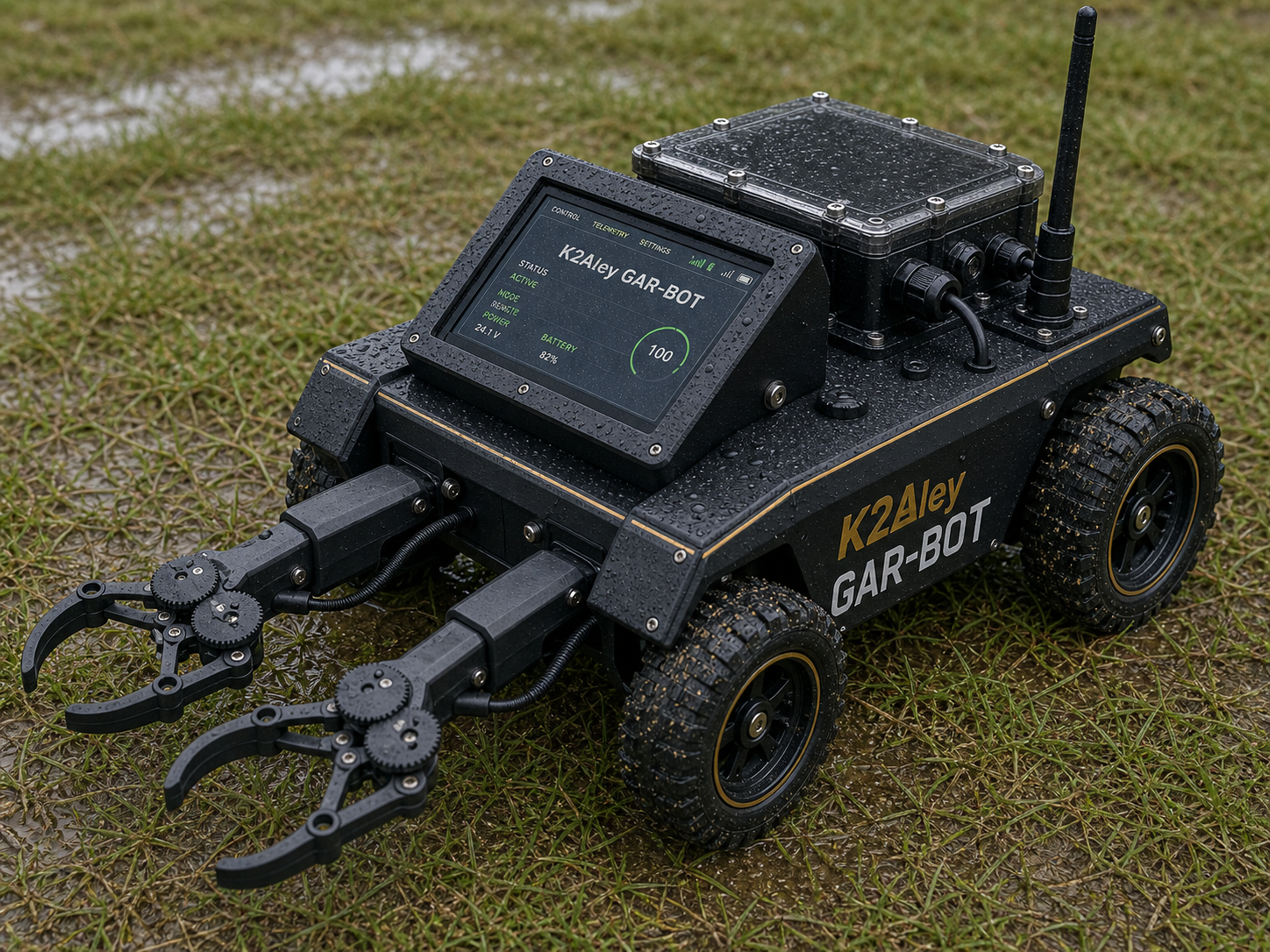
GAR-BOT final layout reference with two top-shoulder claws, 7 inch touchscreen, protective body, and covered electronics.
Reference for the two top-mounted claw shapes and pivots.
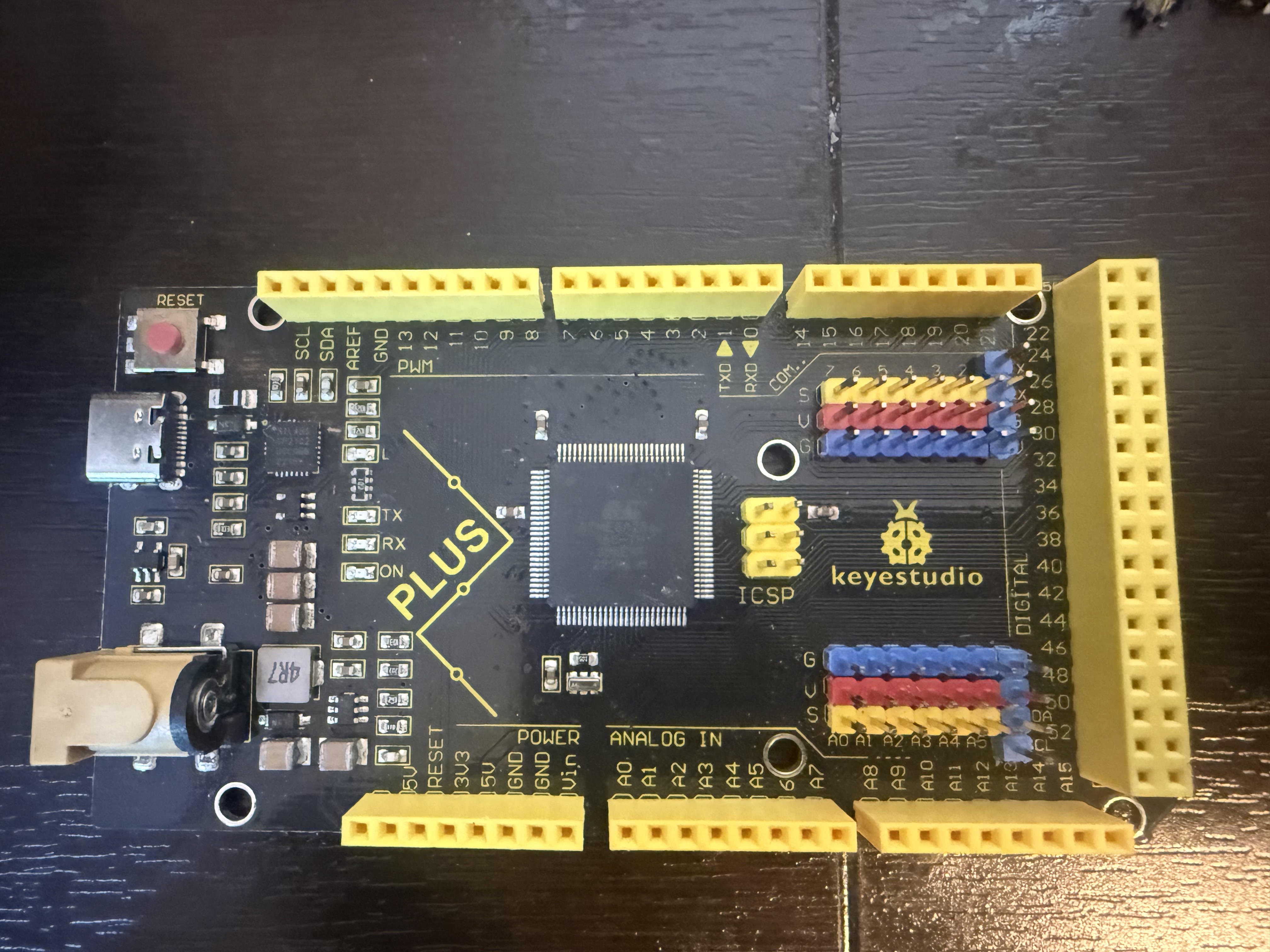
One board per claw for servo channels.
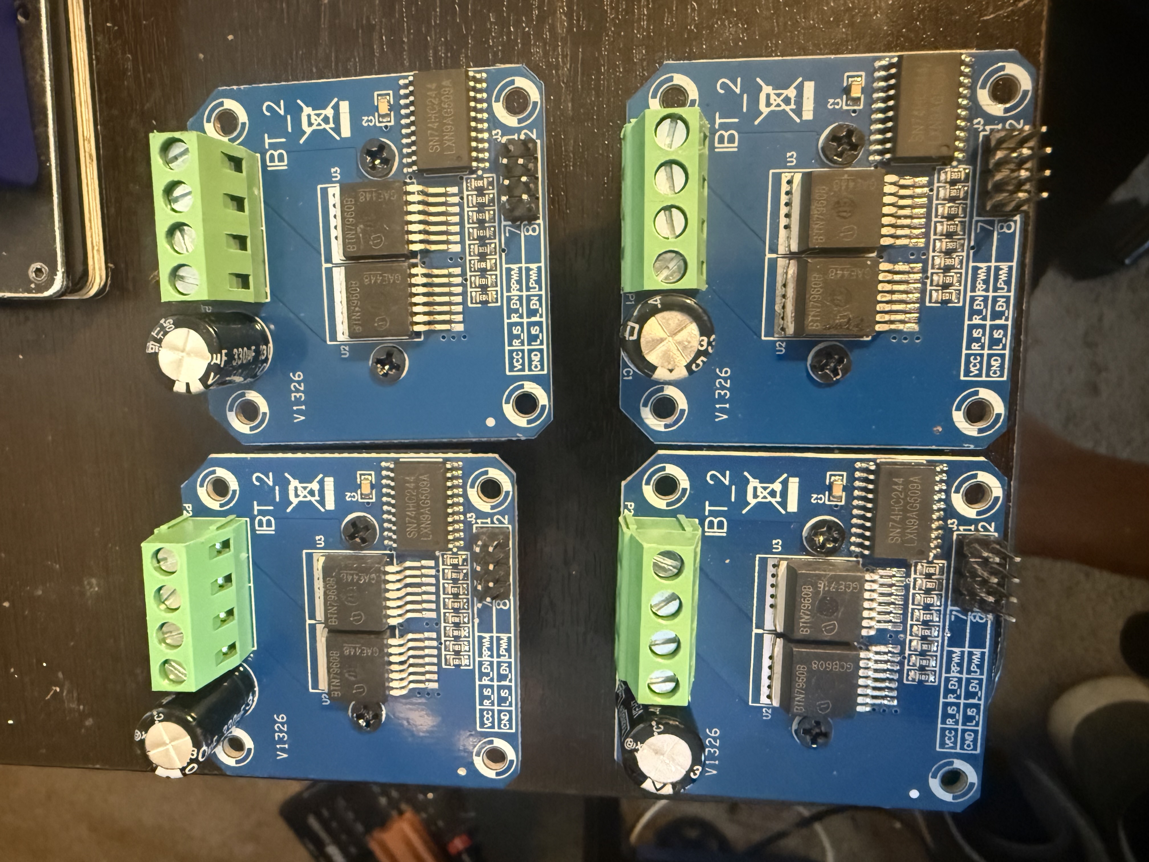
Four motor drivers, one for each drive motor.
Install under the chassis with a fused lighting supply. Add clear sealed pods/lenses before any splash testing.
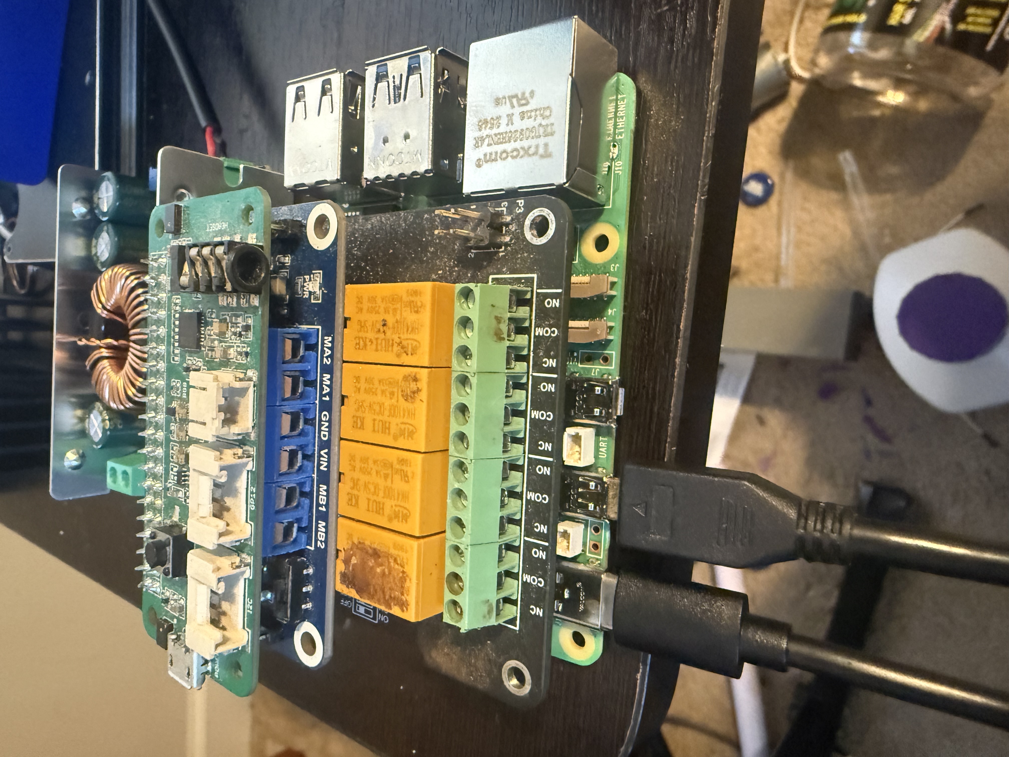
Main robot controller stack inside the protective electronics bay.
The complete BOM is available as a web page, Markdown file, and CSV file.
| Group | Qty | Main BOM Items |
|---|---|---|
| Controller and interface | 1 set | Raspberry Pi 5 with Wi-Fi, RP5 relay HAT, Pico Voice on I2C-1 using SDA P3 and SCL P5, 7 inch USB touchscreen. |
| Drive and power | 4 motors / 4 drivers | Direct-drive 24V gear motors, IBT-2 motor drivers, batteries, fuse, e-stop, buck converters, common ground block. No chain or sprocket drive. |
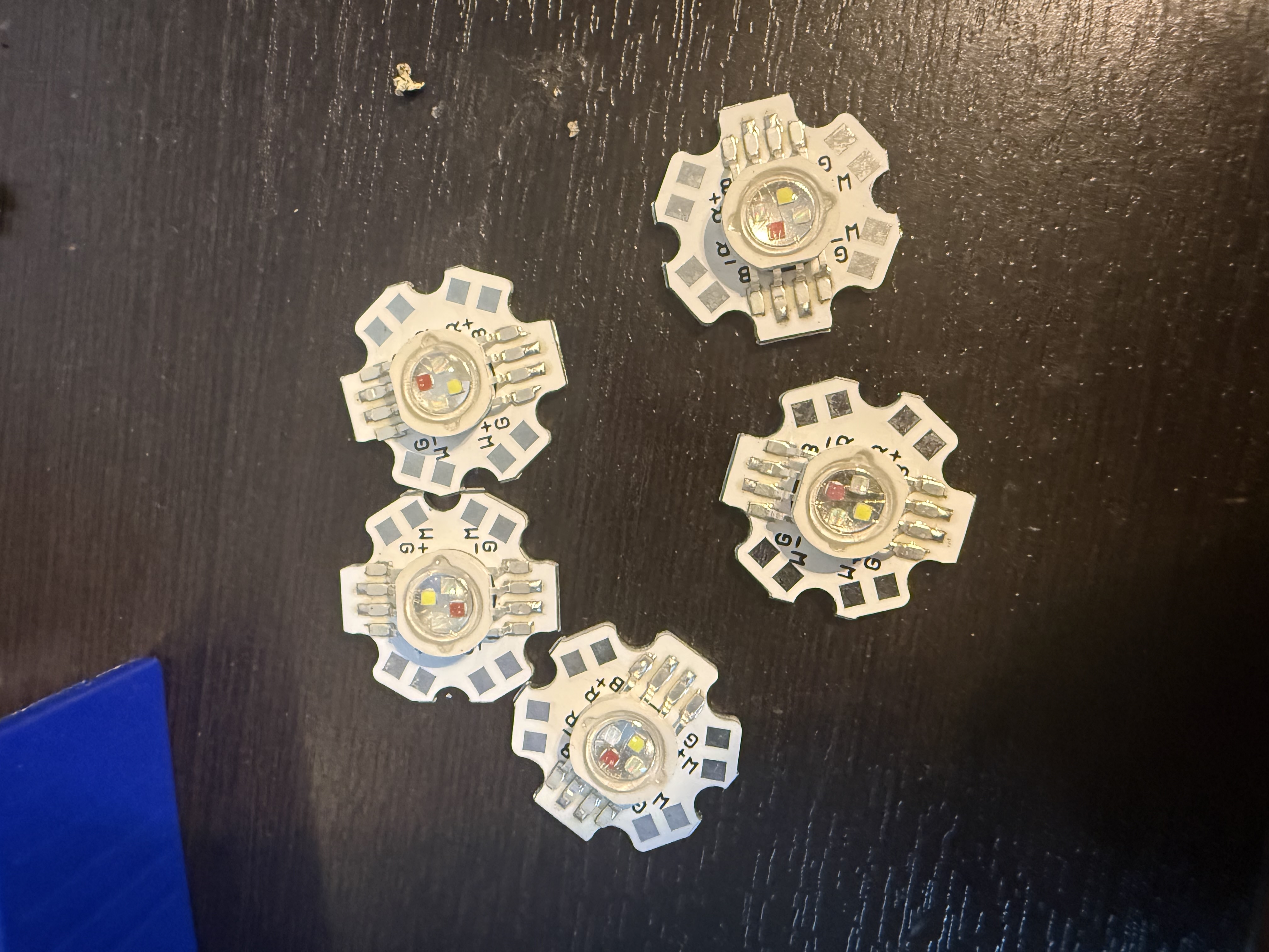
| Ground-effect lighting | 9 LED modules / 2 servos | Nine underbody RGB LED star modules, fused lighting branch, LED supply, RGB driver/MOSFET board, clear pods/lenses for the sealing upgrade, and left/right side-mounted up/down tilt servos. |
| Two claws | 2 sets | Two Keyestudio-style servo controller boards, 12 servos, left/right claw printed assemblies. |
| Remote transmitter | 1 set | RP Zero 2 W with Wi-Fi, Pico Voice board, LoRa transmitter path, 5V power, printed remote enclosure. |
| Sealing upgrade | As needed | Cable glands, USB bulkheads, SMA bulkhead, gasket material, conformal coating, dielectric grease, stainless screws. Required before any splash testing. |
| 3D printed parts | 43 STL files | Frame, one-piece bottom skid plate, protective electronics bay, one-piece large top cover, touchscreen mount, claw parts, remote case, branding badges. |
Files: BOM web page, Markdown BOM, CSV BOM.
Print the structural parts first. Remove support material, deburr cable slots, dry-fit all mating faces, and install M3 heat-set inserts before final assembly.
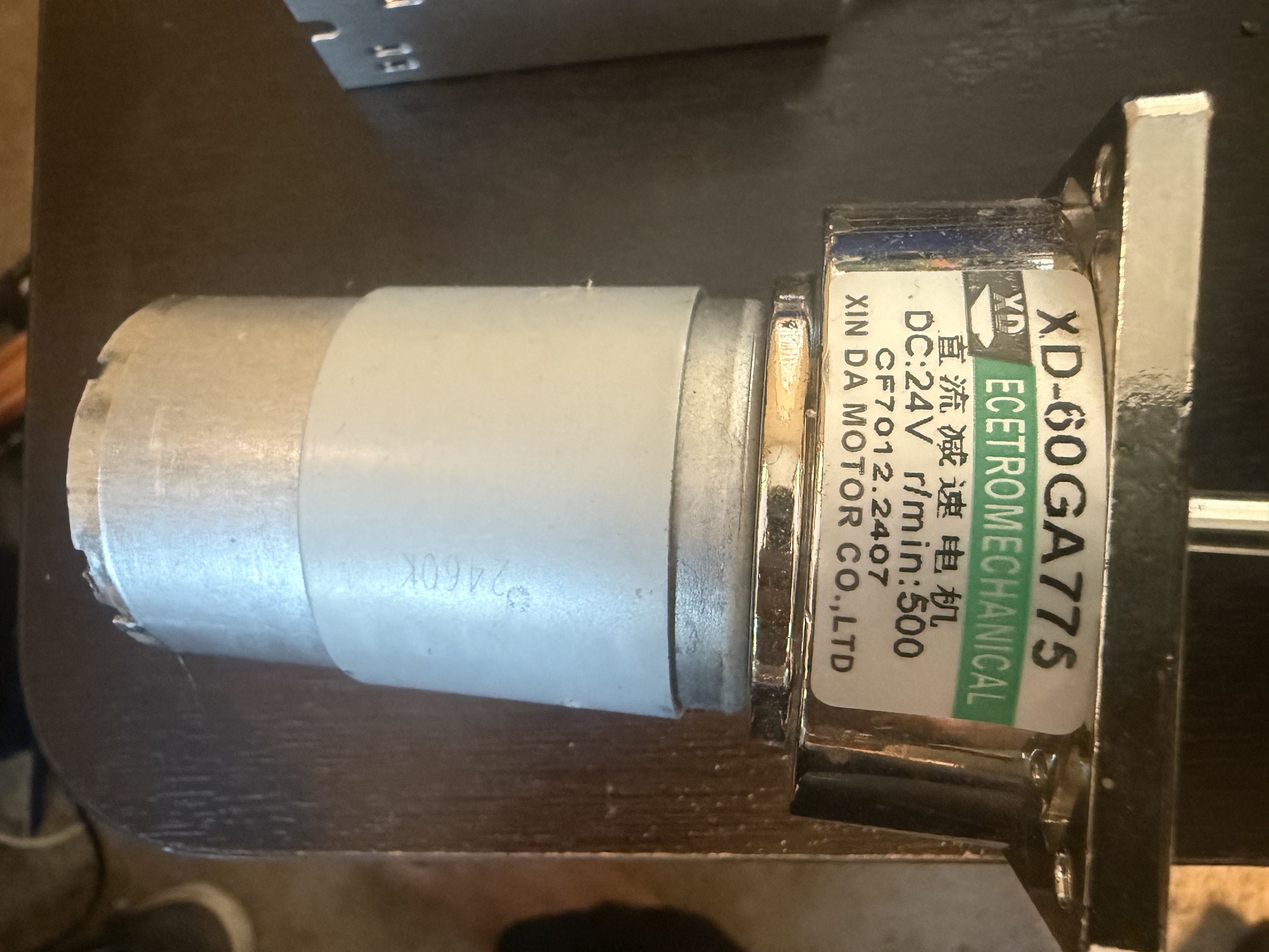
Mount each motor at a wheel corner so it direct-drives its own wheel. Route motor leads away from signal wires. Install IBT-2 covers, buck converter cover, splash shields, and drip-loop clips before wet testing.
Mount the Raspberry Pi 5, buck converter, and Pico Voice board on the electronics bay's internal standoffs. Use RP5 Wi-Fi for SSH, setup, touchscreen/API service, and local maintenance. Wire Pico Voice to I2C-1: SDA to GPIO2 physical pin 3, SCL to GPIO3 physical pin 5, plus shared ground and board-rated power. Route all external wires through the gland panel, then seal the lid.
Bolt the uprights to the deck, attach the top tie bar, seat the screen in the bezel, and fit the rain hood. Check cable strain relief before closing the electronics bay.
Bolt the left and right base mounts down onto the top pads of the shoulder bridge. Add shoulder pivots, servo pockets, wrist cradles, palms, fingers, link bars, gear guards, wire covers, and controller covers.
Bench-test one LED board first to identify the common pad and current requirement. Mount the nine modules under the chassis behind clear gasketed pods/lenses, then route the wires back through cable glands to the lighting driver.
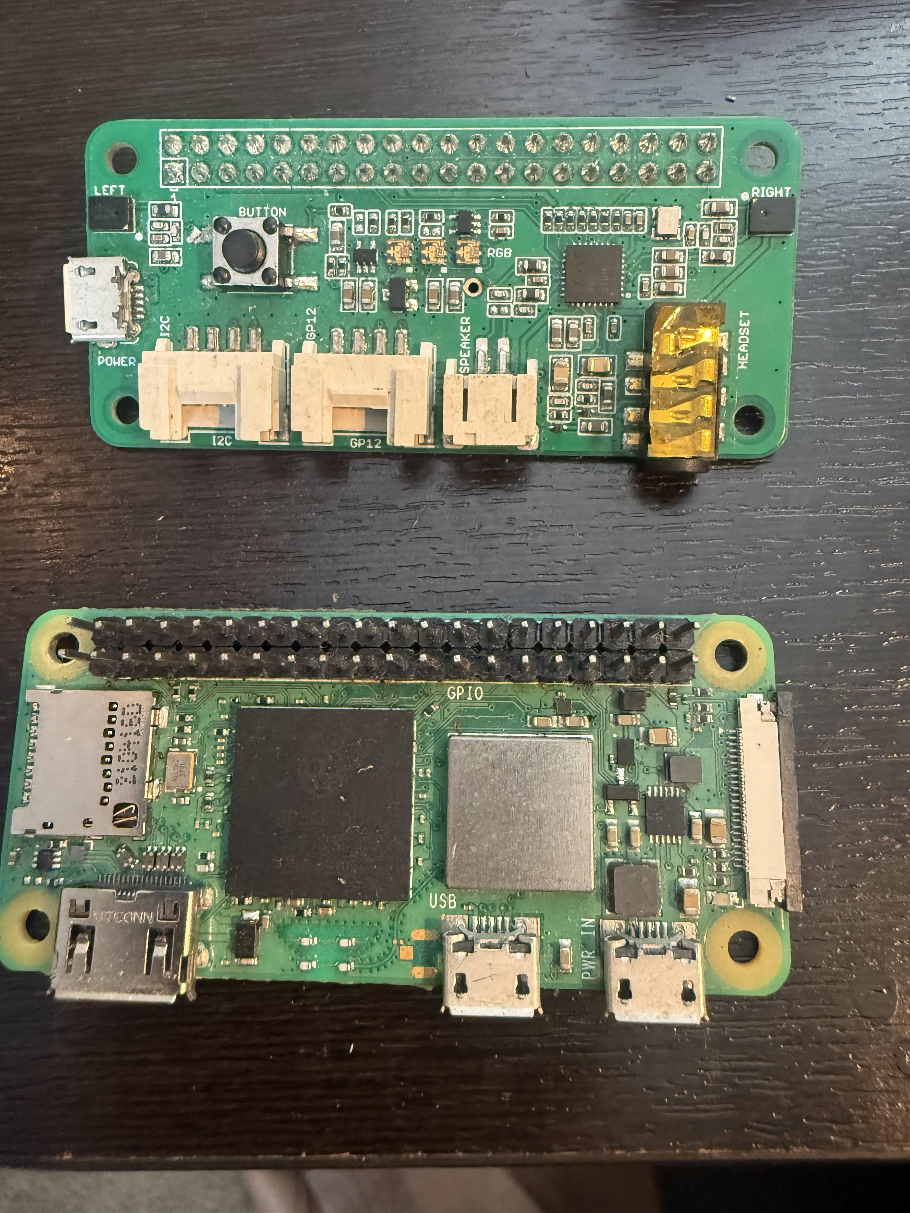
Place the Raspberry Pi Zero 2 W and Pico Voice board inside the remote case. Use Zero 2 W Wi-Fi for SSH, Picovoice setup, and short-range LAN command tests. Mount the LoRa antenna bulkhead through the wall and verify the remote boots before closing the case.
Install the lid badge, side badges, and water warning badge after wiring and sealing checks are complete. Keep badges clear of gasket surfaces and service screws.
Use the visual wiring diagram gallery for the reference-style wire routes, then use the connection map for exact pin tables.
| System | Connection Rule | Check Before Power |
|---|---|---|
| 24V motor bus | Battery pack to main fuse, emergency stop, switched 24V bus, then IBT-2 motor drivers. | Fuse installed, e-stop opens bus, no loose strands. |
| RP5 power | 24V-to-5V buck output feeds Pi 5 at 5.1V with common ground. | Measure voltage with multimeter before plugging in RP5. |
| Servo power | Servo buck feeds Keyestudio servo V/G rows. Pi does not power servos. | Servo voltage is correct and ground is common. |
| Ground-effect lighting | 24V switched bus to lighting fuse, LED supply, RGB driver/MOSFET board, then nine underbody LED modules in three banks. Servo buck powers the left/right side-mounted up/down servos; spare claw-board channels provide signal. | No bare LED PCB exposed; module voltage/current, common anode/cathode, and both servo travels verified. |
| USB | RP5 has four USB ports: left claw, right claw, touchscreen, LoRa/radio bridge or hub. | Pico Voice is on I2C, not USB; keep SDA/SCL at 3.3V logic. |
| Wi-Fi | Both Raspberry Pi 5 and Raspberry Pi Zero 2 W have Wi-Fi for SSH, setup, API testing, and short-range LAN command tests. | Both Pis join the expected LAN and respond at their assigned IPs. |
| Remote | RP Zero 2 W connects to Pico Voice and LoRa path. | Remote boots, Pico Voice audio is detected, and LoRa RF delivery is verified before field driving. |
GAR-BOT is not designed for submersion, pressure washing, or deep standing water.